Istio Part 2: Ambient Mode Under the Hood via Envoy Configs
The original version of this post is available on the Channel.io Tech Blog.
Hi, this is Jetty (Jaehong Jung) and Dylan from the Channel.io DevOps team.
In Part 1, we briefly covered the components and operating principles of Ambient mode. We explained that HBONE is a combination of HTTP/2 CONNECT and mTLS, and that ztunnel transparently redirects traffic, but we didn’t cover how this is actually implemented.
In this post, we’ll look directly into Envoy configs to see how the concepts explained in Part 1 are implemented. We’ll trace the journey of a single HTTP request from the Istio Gateway to a Pod using Envoy configs.
- Part 1: Why Istio Ambient Mode?
- Part 2: Ambient Mode Under the Hood via Envoy Configs (this post)
- Part 3: Surprising Issues and Troubleshooting in Production
Envoy Fundamentals
Listener → Route → Cluster → Endpoint
If you’re already familiar with Envoy’s internal structure, feel free to skip this section.
In Istio, Gateway, Sidecar, and Waypoint are distinguished by role, but in reality they are Envoy Proxies with different configurations injected. To understand Envoy’s behavior, we first need to understand the basic flow of how Envoy processes requests.
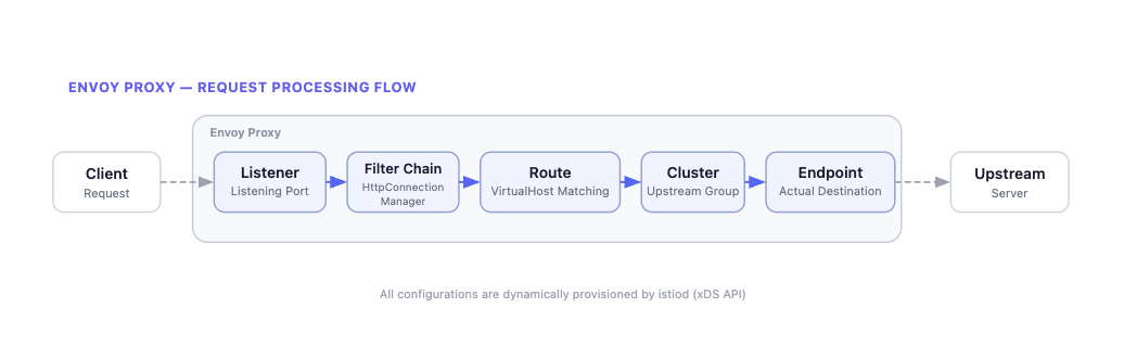
Envoy processes requests in the following order:
- Listener: Receives traffic on a specific port and determines which Filter Chain to process it with.
- Filter Chain: Defines the processing logic for received traffic. For HTTP traffic,
HttpConnectionManageris the representative example. - Route: Determines which Cluster to send requests to based on Virtual Hosts. Routes based on domain names and path patterns.
- Cluster: A logical group of endpoints providing the same service. Load balancing policies (Round Robin, Least Request, etc.) apply here.
- Endpoint: The final destination where traffic is actually delivered. Typically a Pod’s
IP:Portcombination.
In Istio, these configurations are propagated by istiod (control plane) to each Envoy proxy via the xDS API. Whenever the Kubernetes cluster state changes (Pod created/deleted, routing policy changes, etc.), istiod delivers the updated config to each Envoy.
Tracing Gateway’s Envoy Config
As an example, let’s trace step by step how an HTTP request coming into “api.channel.io” passes through the Gateway and reaches a Pod (e.g., ch-dropwizard-public). We’ll first explain the overall flow of the HTTP request. Details will be covered in each subsequent step.
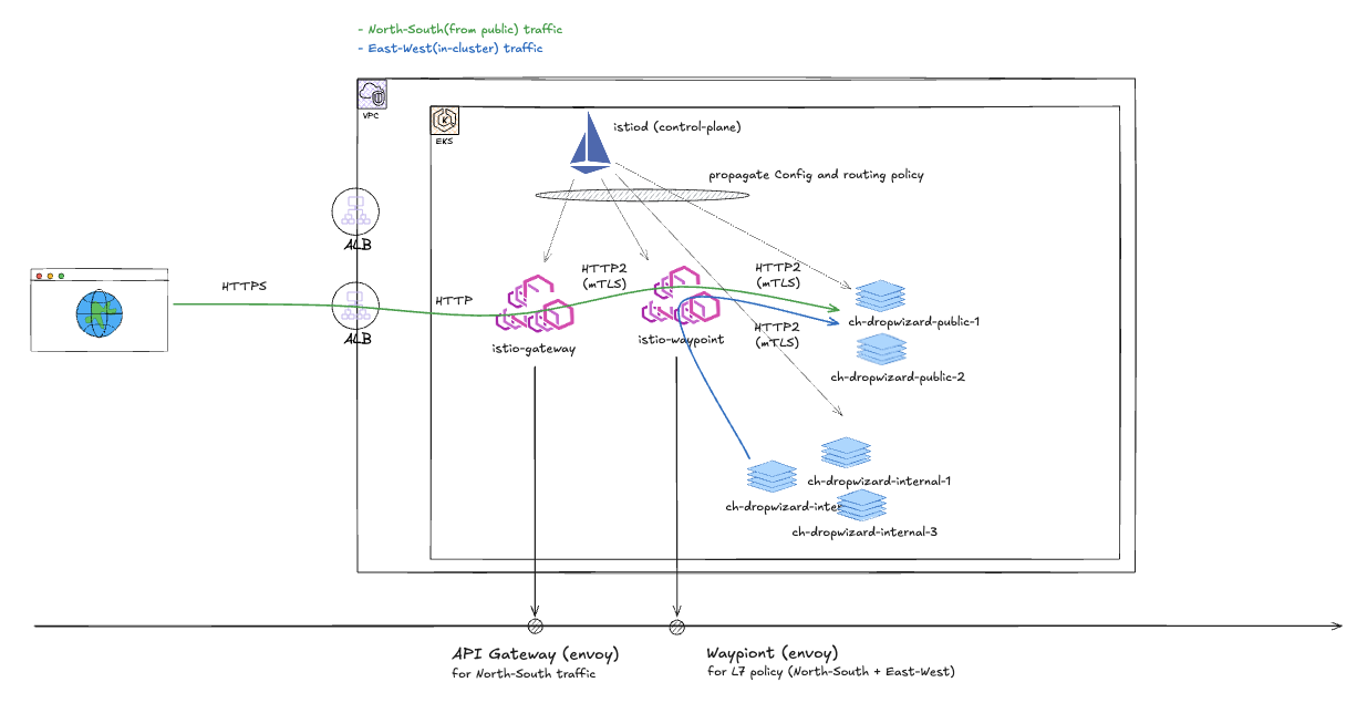
The diagram above shows our team’s current Istio Gateway configuration. HTTP requests from the Public Internet reach the destination Pod in the order: AWS ALB → Istio Gateway → Istio Waypoint.
An important note here is that this architecture is not the default behavior of Istio Ambient mode. In the default behavior, the Istio Gateway delivers traffic directly to the backend Pod through the destination Pod’s ztunnel. That is, in the default configuration, north-south traffic follows the Gateway → Pod path, not Gateway → Waypoint → Pod. The Waypoint proxy originally exists as a component for applying L7 policies to east-west traffic between in-mesh Pods.
To route through a Waypoint from the Gateway, you must explicitly add the
istio.io/ingress-use-waypoint=truelabel along with theistio.io/use-waypointlabel.
So why did our team choose to route through a Waypoint instead of using the default behavior? With the default behavior, routing policies for public traffic (north-south) and in-mesh traffic (east-west) are applied in different places (once at the Gateway, once at the Waypoint). We determined this would create cognitive overhead from having to manage routing policies in two places for the same service.
We adopted an approach of clearly separating responsibilities. The Gateway only handles edge roles like hostname matching, while routing policies and L7 policies are all managed centrally at the waypoint. For this purpose, we use istio.io/ingress-use-waypoint=true by default, and this post also explains Envoy configs based on the Gateway → Waypoint → Pod path.
For more details, see the Ambient Mesh docs.
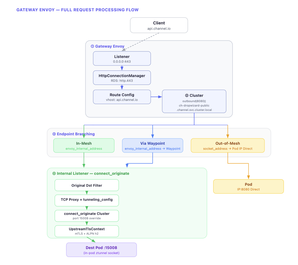
The diagram above summarizes the overall flow of request processing in the Gateway Envoy. Starting from the Listener, it proceeds through Route → Cluster → Endpoint, and at the Endpoint stage, the path diverges based on the destination’s mesh participation status. Let’s now examine the actual Envoy config for each step.
The Envoy configs we’ll cover can be checked using the istioctl proxy-config command.
istioctl proxy-config listener <gateway-pod> -n istio-system
istioctl proxy-config route <gateway-pod> -n istio-system
istioctl proxy-config cluster <gateway-pod> -n istio-system
istioctl proxy-config endpoint <gateway-pod> -n istio-system
1. Active Listener: Virtual Host Matching and Routing
The Gateway’s 0.0.0.0:443 listener receives HTTP requests. This listener’s Filter Chain has HttpConnectionManager configured, which dynamically receives a route config named http.443 through RDS (Route Discovery Service).
{
  "name": "0.0.0.0_443",
  "address": {
    "socket_address": {
      "address": "0.0.0.0",
      "port_number": 443
    }
  },
  "filter_chains": [
    {
      "filters": [
        {
          "name": "envoy.filters.network.http_connection_manager",
          "typed_config": {
            "route_config_name": "http.443",
            "rds": {
              "config_sources": [
                {
                  "ads": {}
                }
              ]
            # ...
The route config contains a list of Virtual Hosts, and it finds the Virtual Host matching the request’s Host header to route to the corresponding Cluster.
{
  "name": "http.443",
  "virtual_hosts": [
    {
      "name": "api.channel.io",
      "domains": ["api.channel.io"],
      "routes": [
        {
          "match": {
            "prefix": "/"
          },
          "route": {
            "cluster": "outbound|8080||ch-dropwizard-public.channel.svc.cluster.local",
            "timeout": "30s"
          }
        # ...
Up to this point, it’s not much different from a typical Envoy proxy. Requests to api.channel.io are routed to the outbound|8080||ch-dropwizard-public.channel.svc.cluster.local cluster. This cluster name is an Istio auto-generated convention in the format outbound|{port}||{service}.{namespace}.svc.cluster.local.
2. Endpoint Selection and Transport Socket
Once the cluster is determined, the next step is deciding which Endpoint within that cluster to send to. This is the most interesting point in Ambient mode. The same cluster (outbound|8080||ch-dropwizard-public) has completely different endpoint configurations depending on the destination Pod’s mesh participation status.
Let’s start with the simplest case and work through them one by one.
When the Destination Is Out-of-mesh
First, the case where traffic is headed to a Pod not participating in the mesh.
{
"address": {
"socket_address": {
"address": "10.90.165.200",
"port_number": 8080
}
},
"load_balancing_weight": 1,
"metadata": {
"filter_metadata": {
"envoy.transport_socket_match": {}
}
}
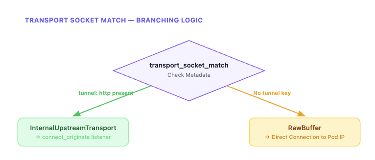
}It connects directly to the Pod IP using the socket_address as-is. Since there’s no tunnel key in transport_socket_match, the default tlsMode-disabled (RawBuffer) is applied according to matching rules. Traffic is delivered directly in plaintext without HBONE tunneling, bypassing the internal listener.
When the Destination Is In-mesh
Now let’s look at the case where the destination Pod is part of the mesh. Compared to out-of-mesh, the structure is markedly different.
{
  "endpoint": {
    "address": {
      "envoy_internal_address": {
        "server_listener_name": "connect_originate"
      }
    }
  },
  "metadata": {
    "filter_metadata": {
      "envoy.transport_socket_match": {
        "tunnel": "http"
      },
      "envoy.filters.listener.original_dst": {
        "local": "10.90.165.200:8080"
      }
    }
  }
}
This structure may look unfamiliar at first. Let’s break it down.
envoy_internal_address doesn’t point to an actual network address but to Envoy’s internal user space communication. server_listener_name: connect_originate means it connects to an internal listener named connect_originate that exists within Envoy. In other words, traffic isn’t going out to the network but is being passed to another listener inside Envoy.
The metadata side is also important. When tunnel: http is set in envoy.transport_socket_match, a special transport socket called InternalUpstreamTransport is selected according to the cluster’s transport_socket_matches rules. This socket’s role is to pass metadata from the envoy.filters.listener.original_dst namespace to the internal listener. As a result, the actual destination address (local: 10.90.165.200:8080) can reach the internal listener.
When the Destination (In-mesh) Has a Waypoint Configured
Finally, the case where a waypoint proxy is configured for an in-mesh destination. The basic structure is similar to in-mesh, but a waypoint key is added to the metadata.
{
  "endpoint": {
    "address": {
      "envoy_internal_address": {
        "server_listener_name": "connect_originate"
      }
    }
  },
  "metadata": {
    "filter_metadata": {
      "envoy.transport_socket_match": {
        "tunnel": "http"
      },
      "envoy.filters.listener.original_dst": {
        "local": "172.20.134.88:8080",
        "waypoint": "10.90.165.200:15008"
      }
    }
  }
}
The key difference from in-mesh is that a waypoint key is added to the original_dst metadata. The local value is the Service ClusterIP (172.20.134.88:8080) rather than the final Pod IP, because the waypoint handles final Pod selection. As a result, traffic flows in the order: Gateway → HBONE → waypoint → HBONE → destination Pod.
In summary, all three cases use the same cluster, but the traffic path differs completely depending on the endpoint’s metadata and transport socket configuration. The core of this branching is transport_socket_match.
3. Internal Listener and HBONE Tunneling
This is the flow after transitioning from the in-mesh (or Waypoint) endpoint to the connect_originate internal listener via envoy_internal_address. This process is the actual implementation of “HBONE” as explained in Part 1.
The connect_originate listener is declared as an internal_listener. Unlike regular listeners, it doesn’t open a network port and operates only within Envoy’s internal user space.
{
  "name": "connect_originate",
  "internal_listener": {},
  "filter_chains": [
    {
      "filter_chain_match": {
        "application_protocols": ["http/1.1", "h2"]
      },
      "filters": [
        {
          "name": "envoy.filters.listener.original_dst"
        },
        {
          "name": "envoy.filters.network.tcp_proxy",
          "typed_config": {
            "stat_prefix": "connect_originate",
            "cluster": "connect_originate",
            "tunneling_config": {
              "use_connect": true,
              "connect_config": {
                "protocol": "HTTP/2",
                "allow_absolute_url": true
              },
              "headers_to_add": [
                {
                  "header": {
                    "key": ":authority",
                    "value": "%FILTER_STATE(envoy.filters.listener.original_dst:local_address)%"
                  }
                }
              ]
            # ...
First, the original_dst listener filter reads metadata passed from the previous stage via InternalUpstreamTransport. Then the tcp_proxy filter connects to the connect_originate cluster, using the hostname configured in tunneling_config as the :authority header for the HTTP/2 CONNECT request.
The connect_originate cluster is a special cluster of type ORIGINAL_DST.
{
  "name": "connect_originate",
  "type": "ORIGINAL_DST",
  "connect_timeout": "10s",
  "lb_policy": "CLUSTER_PROVIDED",
  "original_dst_lb_config": {},
  "upstream_port_override": 15008,
  "transport_socket": {
    "name": "envoy.transport_sockets.tls",
    "typed_config": {
      "common_tls_context": {
        "tls_certificate_sds_secret_configs": [
          {
            "name": "default"
          }
        ]
      },
      "sni": "%FILTER_STATE(envoy.filters.listener.original_dst:local_address)%"
    }
  }
}
This cluster doesn’t use EDS (Endpoint Discovery Service) but dynamically determines the upstream host from downstream connection metadata. upstream_port_override: 15008 overrides the port to ztunnel’s HBONE receiving port. The transport socket has UpstreamTlsContext configured, applying ALPN h2 (HTTP/2) and SPIFFE ID-based mTLS authentication.
In the Waypoint case, a metadata_key is additionally configured in original_dst_lb_config, reading the waypoint metadata passed from the endpoint to dynamically override the destination address to the waypoint address. At this point, the :authority header is set to the originally intended destination (Service ClusterIP), so the waypoint can use this to route to the final Pod.
The entire process can be summarized in the following diagram.
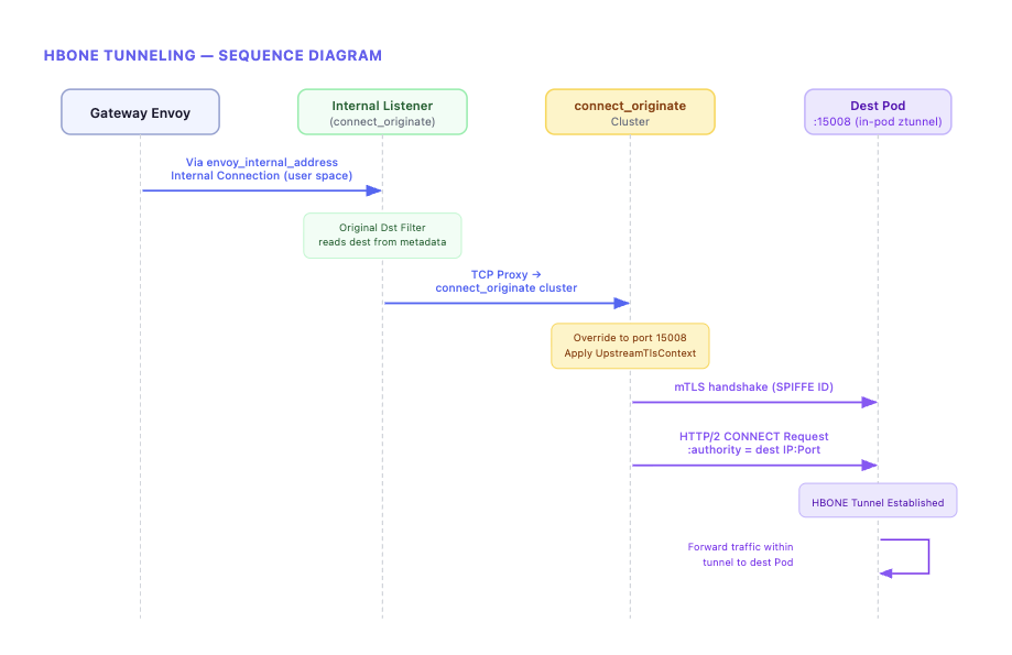
In Part 1, we said “HBONE might sound like a complex separate protocol by name, but its essence is a combination of existing Envoy features.” Now we’ve confirmed what that combination specifically is. Passing metadata via InternalUpstreamTransport, generating HTTP/2 CONNECT requests through tcp_proxy’s tunneling_config, and establishing mTLS via UpstreamTlsContext — these three are the core of HBONE.
ztunnel’s Traffic Redirection: iptables and Cross-Namespace Sockets
Above, we saw the process of traffic reaching the destination node’s ztunnel from the Gateway. Now let’s look at the other side — how ztunnel can intercept a Pod’s traffic.
In Part 1, we only explained that “istio-cni injects iptables rules and ztunnel transparently redirects traffic,” but looking at the actual implementation reveals a surprisingly sophisticated mechanism at work.
istio-cni’s Role and ztunnel Socket Creation
ztunnel is a DaemonSet separate from Pods. So how can it intercept a Pod’s traffic? The key is that ztunnel creates sockets directly inside the Pod’s network namespace.
This process is achieved through the collaboration of three components.
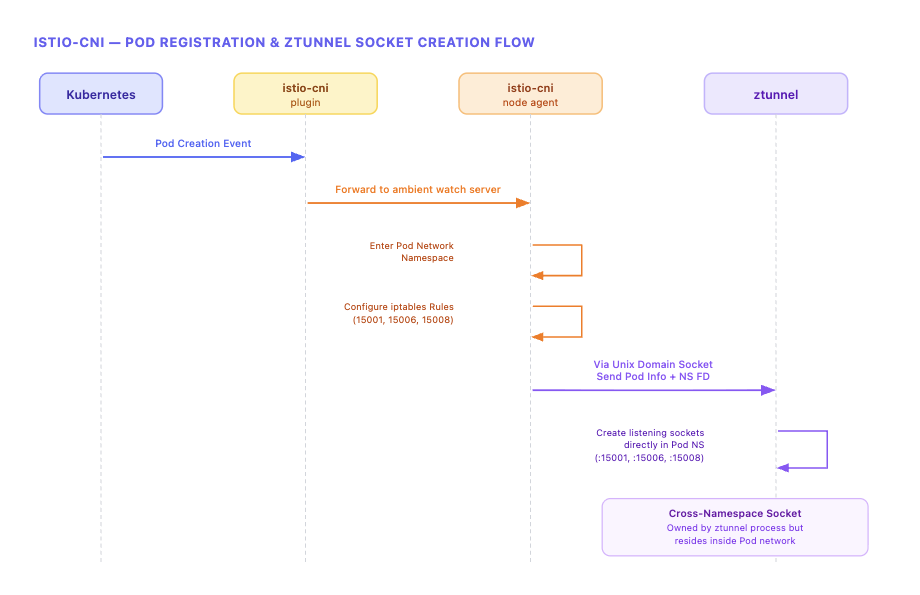
The istio-cni plugin (binary) is installed as a chained CNI plugin, detecting Pod creation events and forwarding them to the istio-cni node agent. The istio-cni node agent handles the actual network configuration. It enters the Pod’s network namespace to set up iptables rules, and passes Pod information and network namespace file descriptors (FDs) to ztunnel via Unix Domain Sockets.
ztunnel uses the received network namespace FD to create listening sockets directly within the Pod namespace using low-level Linux socket APIs. This is the reality of the “in-pod ztunnel” mentioned in Part 1. From inside the Pod, there are listening sockets on localhost ports 15001/15006/15008, but these sockets are owned by the ztunnel DaemonSet process.
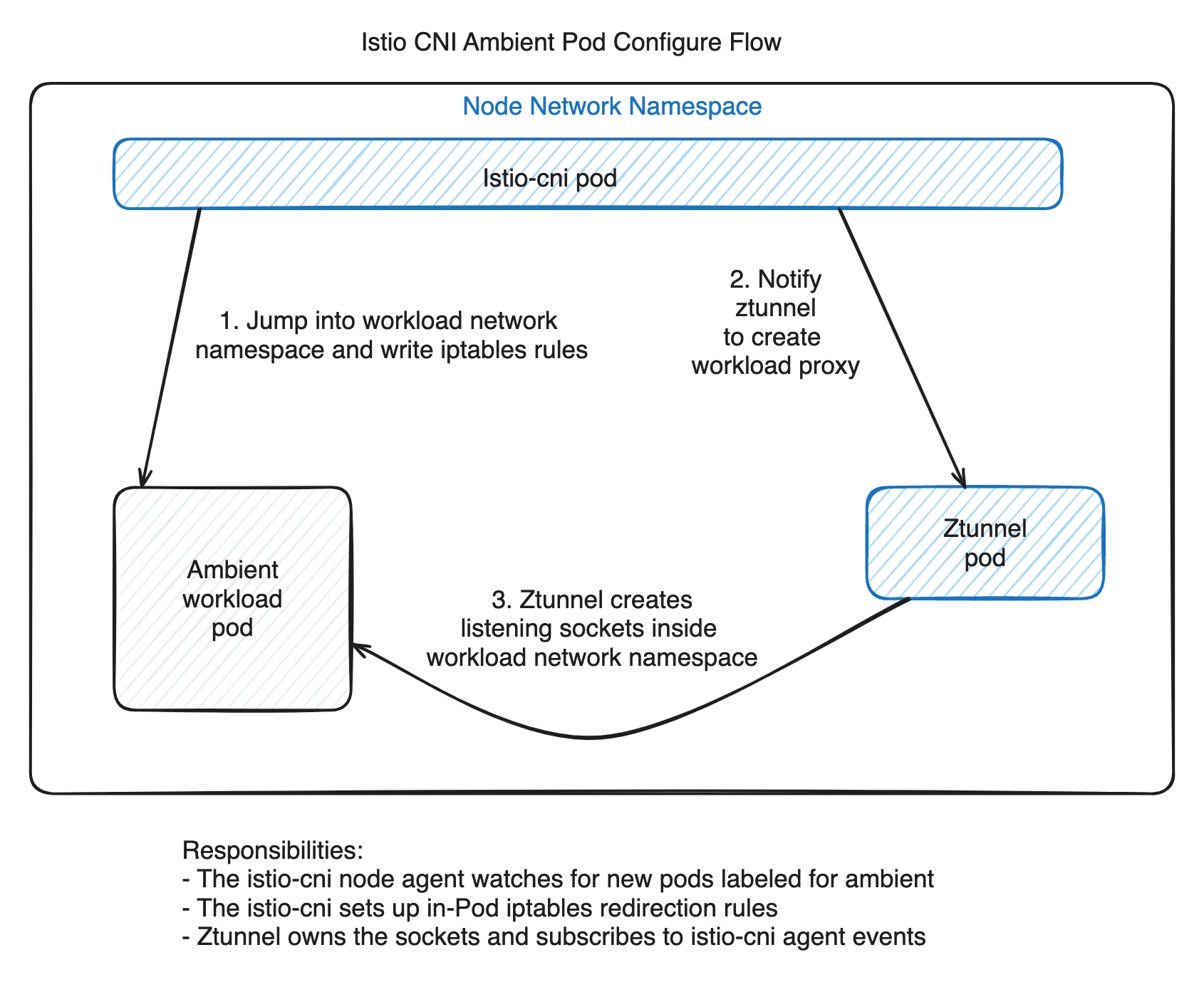
The result is the structure shown above.
In Part 1, we mentioned that “the actual target of redirection is not the ztunnel container but the sockets inside the Pod connected to ztunnel.” Now the mechanism is concretely visible. The ztunnel process operates at the Node level, but through cross-namespace socket creation, it has a foothold inside the Pod network.
iptables Rule Analysis
Let’s examine the actual iptables rules that the istio-cni node agent sets up in the Pod network namespace.
*mangle
-A PREROUTING -j ISTIO_PRERT
-A OUTPUT -j ISTIO_OUTPUT
-A ISTIO_PRERT -m mark --mark 0x539/0xfff -j CONNMARK --set-xmark 0x111/0xfff
-A ISTIO_OUTPUT -m connmark --mark 0x111/0xfff -j CONNMARK --restore-mark --nfmask 0xffffffff --ctmask 0xffffffff
COMMIT

*nat
-A OUTPUT -j ISTIO_OUTPUT
-A PREROUTING -j ISTIO_PRERT
-A ISTIO_PRERT -s 169.254.7.127 -p tcp -m tcp -j ACCEPT
-A ISTIO_OUTPUT -d 169.254.7.127 -p tcp -m tcp -j ACCEPT
-A ISTIO_PRERT ! -d 127.0.0.1/32 -p tcp ! --dport 15008 -m mark ! --mark 0x539/0xfff -j REDIRECT --to-ports 15006
-A ISTIO_OUTPUT -p tcp -m mark --mark 0x111/0xfff -j ACCEPT
-A ISTIO_OUTPUT ! -d 127.0.0.1/32 -o lo -j ACCEPT
-A ISTIO_OUTPUT ! -d 127.0.0.1/32 -p tcp -m mark ! --mark 0x539/0xfff -j REDIRECT --to-ports 15001
COMMIT
The rules look complex, but they become easier to understand when divided into two directions: Ingress (incoming traffic) and Egress (outgoing traffic).
169.254.7.127is an SNAT IP used to distinguish kubelet health check probes. (cni/pkg/nodeagent/options.go:44)
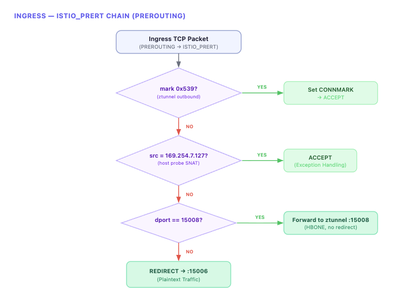
Ingress: ISTIO_PRERT Chain
All incoming TCP traffic to the Pod passes through the ISTIO_PRERT chain at the PREROUTING stage.
Egress: ISTIO_OUTPUT Chain
All outgoing TCP traffic from the Pod passes through the ISTIO_OUTPUT chain at the OUTPUT stage.
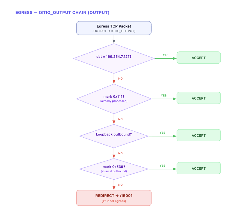
All outbound TCP traffic is REDIRECTED to ztunnel’s port 15001. ztunnel applies HBONE encapsulation here before sending to the destination.
Packet Marking
What’s important here is packet marking. ztunnel sets a 0x539 mark on packets it sends. This mark serves two purposes.
-
It prevents an infinite loop where packets sent by ztunnel are redirected back to ztunnel by iptables. All REDIRECT rules in both Ingress (
ISTIO_PRERT) and Egress (ISTIO_OUTPUT) have the! --mark 0x539condition, so packets sent by ztunnel skip redirection. -
It also prevents redirection of response packets via
CONNMARK. When ztunnel delivers traffic to the app (withmark 0x539), a0x111connmark is recorded on that connection in thePREROUTINGmangle table. When the app later sends a response on the same connection, the connmark0x111is restored as a packet mark in the OUTPUT mangle table, and themark 0x111 → ACCEPTrule in the nat table allows it to pass through without REDIRECT. In other words, responses to connections initiated by ztunnel go out directly without passing through ztunnel again.
In summary:
0x539(packet mark): Identifies packets directly sent by ztunnel → prevents redirection0x111(connection mark): Identifies response packets from connections initiated by ztunnel → prevents redirection
Summary: The Complete Journey of a Single Request
Let’s combine everything we’ve examined step by step into a single flow.
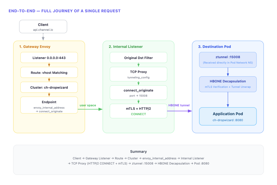
When a client request arrives at the Gateway Listener, the Route determines the Cluster through Virtual Host matching. If the Cluster’s Endpoint is set to envoy_internal_address, it connects to the connect_originate Internal Listener inside Envoy. The Internal Listener’s TCP Proxy generates an HTTP/2 CONNECT request through tunneling_config and establishes mTLS via UpstreamTlsContext to complete the HBONE tunnel. Traffic reaching the destination node’s Pod through this tunnel is received by ztunnel’s 15008 socket — listening directly within the Pod network namespace — which decapsulates the HBONE and delivers it to the final application Pod.
We’ve confirmed that HBONE, ztunnel, and traffic redirection — conceptually explained in Part 1 — are actually implemented through concrete mechanisms: Envoy’s internal listener, transport socket match, tunneling config, and iptables REDIRECT.
Preview of the Next Post
In this post, we traced the normal request flow at the Envoy config level. In the next post, we’ll cover the issues we encountered while applying Ambient mode in production — particularly how we tracked down and resolved 503 errors and Half-Open (stale) Connection problems.
This is the second post in the Istio Ambient Mode adoption series.
- Part 1: Why Istio Ambient Mode?
- Part 2: Ambient Mode Under the Hood via Envoy Configs (this post)
- Part 3: Surprising Issues and Troubleshooting in Production