What I wish I knew before introducing Kafka to Grafana Mimir
The original version of this post is available on the Channel.io Tech Blog.
Hi, I’m Jetty (Jaehong Jung) from the Channel.io DevOps team.
To make our monitoring stack’s ingestion pipeline more resilient, we adopted Grafana Mimir’s Kafka-based ingest-storage architecture. We had two main reasons:
- We wanted an asynchronous buffer between distributors and ingesters so that an ingester failure or a temporary processing delay would not immediately turn into distributor backpressure and lost metrics.
- Kafka-based ingest storage became the stable, preferred architecture in Mimir 3.0, so we considered it the direction we would eventually need to take anyway.
Once we actually implemented it, however, we found many details that are easy to miss if you think of the change as simply “putting Kafka in front of Mimir.” In particular, the way Mimir uses Kafka differs significantly from the familiar producer/consumer model. We usually picture multiple consumers sharing partitions within one consumer group, with Kafka recalculating partition assignments through a rebalance whenever consumers are added or removed.
Mimir ingest storage works differently. An ingester pod’s instance ID—more precisely, the ordinal at the end of its name—is tied directly to a Kafka partition number. mimir-ingester-zone-a-3 consumes partition 3, and mimir-ingester-zone-b-3 also consumes partition 3. Each ingester reads exactly one partition, while ingesters in multiple zones read the same partition for high availability.
This post summarizes what we learned while introducing Kafka to Mimir.
1. Why We Introduced Kafka
Let me start with some context. We had two main reasons for introducing Kafka.
1-1. Stability Through an Asynchronous Buffer
The first was to improve the availability and resilience of our monitoring pipeline by adding an asynchronous buffer.
Mimir’s classic pipeline did not have a durable buffer between distributors and ingesters to absorb backpressure. Problems in the ingester tier directly affected the success rate and latency of the write path. We configured distributor rate limits according to the capacity the ingesters could actually sustain. Continuously accepting more than the ingesters could handle could spread an incident across the entire metrics infrastructure, so distributors rejected and discarded writes above a certain threshold with 429 responses. This protected us from the worst-case scenario, but we still saw several 429 incidents in production and lost a corresponding amount of metrics. Conversely, setting the rate limit too loosely overloaded and destabilized the ingesters, which could also lead to incidents.
In our metrics pipeline, Prometheus replicas in several Kubernetes clusters collect metrics and remote-write them directly to Mimir distributors in a central monitoring cluster.
flowchart LR
    subgraph C1["spoke cluster A"]
        P1["Prometheus replicas"]
    end
    subgraph C2["spoke cluster B"]
        P2["Prometheus replicas"]
    end
    subgraph C3["spoke cluster C"]
        P3["Prometheus replicas"]
    end
    subgraph HUB["hub monitoring cluster"]
        D["mimir-distributor"] -->|"quorum write"| I["mimir-ingesters<br/>RF=3"]
    end
    P1 -->|"remote_write"| D
    P2 -->|"remote_write"| D
    P3 -->|"remote_write"| D
It is important to identify the exact success boundary for writes here. In Mimir’s classic architecture, a distributor does not return success to Prometheus merely because it received the request. It pushes incoming series to ingesters and considers the remote-write request successful only after satisfying the write quorum for the configured replication factor. With RF=3, as in our deployment, the same series must be written to at least two ingesters. If one write fails but the other two succeed, one replica has a gap, but the metric itself has not been dropped.
If the distributor cannot satisfy quorum, it returns a 5xx response instead of success. Prometheus remote write treats 5xx responses as recoverable errors and retries samples still present in its local WAL. A temporary ingester overload or failure therefore does not immediately cause metric loss. However, under the default behavior described in the official Prometheus remote-write guide, if an endpoint outage or backlog lasts more than two hours, unsent data may be lost during WAL compaction.
Without Kafka, exceeding Mimir ingester capacity can lead to data loss through two paths:
- If ingester write quorum failures continue for an extended period, remote-write backlog builds while Prometheus retries the 5xx responses. After two hours, WAL compaction may discard metrics that have not yet been sent.
- Setting distributor rate limits to what the ingesters can sustain protects the pipeline, but the distributor drops requests over the limit and returns 429. Prometheus does not retry 429 responses by default, so unless
retry_on_http_429: trueis configured, those metrics may be lost immediately.
We had a similar pain point in our Loki logging pipeline. An otel-collector DaemonSet in each cluster collects logs and sends them to an otel-collector-gateway Deployment in the central monitoring cluster, which then pushes them to the Loki distributor.
flowchart LR
    subgraph C1["spoke cluster A"]
        O1["otel-collector<br/>DaemonSet"]
    end
    subgraph C2["spoke cluster B"]
        O2["otel-collector<br/>DaemonSet"]
    end
    subgraph HUB["hub monitoring cluster"]
        G["otel-collector-gateway<br/>Deployment"] --> Q["gateway internal<br/>in-memory sending_queue"]
        Q -->|"Push / retry"| D["loki-distributor"]
        D --> I["loki-ingester"]
    end
    O1 -->|"OTLP logs"| G
    O2 -->|"OTLP logs"| G
With the gateway exporter’s sending_queue backed by memory, as in our configuration, the point at which an otel-collector successfully sends logs to the gateway is not the point at which those logs are stored by a Loki ingester. The upstream request can succeed once the gateway accepts the logs into its pipeline and queue. If load or a failure in the Loki ingesters later slows or fails the distributor push, the gateway retries while its queue grows. This queue is neither as large nor as durable as the Prometheus remote-write WAL, so logs not yet delivered to Loki may be lost if it exceeds capacity or the gateway restarts or runs out of memory.
The specific failure modes differed between Mimir and Loki, but they shared the same operational pain point: no durable asynchronous buffer could sufficiently absorb temporary downstream failures and processing delays.
Adopting Mimir ingest storage changes this constraint. A distributor no longer needs to set its rate limit directly against the instantaneous throughput of ingesters, which are difficult to scale out quickly and elastically. Kafka becomes the first destination on the write path and stores the data as a durable buffer. Distributor capacity can therefore be designed around the Kafka cluster’s produce throughput, replication, and broker capacity rather than the ingesters’ immediate throughput. Ingester consumers can catch up with the data in Kafka at their own pace, and transient processing delays become consumer lag.
Kafka is not an infinite buffer, of course. You still need to operate broker throughput, retention, disk capacity, and lag alerts. The important shift is that Mimir’s write path stores the data safely in Kafka first and lets the ingesters catch up.
1-2. The Target Architecture
The second reason was that Kafka-based ingest storage became Mimir 3.0’s target architecture.
The Grafana Labs post on Mimir’s redesigned architecture describes introducing Kafka as an asynchronous buffer between ingestion and queries to decouple the read and write paths as a major architectural change. The official documentation also identifies ingest storage as stable and preferred starting with Mimir 3.0. Kafka was therefore both a short-term way to reduce the impact of incidents and the direction we would eventually need to adopt.
In Mimir’s classic architecture, the write path looks like this:
flowchart LR
    P["Prometheus / remote_write"] --> D["Mimir distributor"]
    D -->|"gRPC Push<br/>RF=3 fan-out"| I1["ingester A"]
    D -->|"gRPC Push"| I2["ingester B"]
    D -->|"gRPC Push"| I3["ingester C"]
    I1 --> S3["Object storage"]
    I2 --> S3
    I3 --> S3
The distributor shards incoming series through the hash ring and pushes them to as many ingesters as the configured replication factor specifies. With RF=3, the same series enters the TSDB head of three different ingesters. A write request succeeds only after reaching quorum. The ingesters are therefore directly on the write path, and their health directly affects the distributor’s write success rate.
With ingest storage, Kafka becomes the end of the write path:
flowchart LR
    P["Prometheus / remote_write"] --> D["Mimir distributor"]
    D -->|"Produce"| K["Kafka / MSK<br/>topic partitions"]
    K -->|"Consume"| I1["ingester zone-a-0"]
    K -->|"Consume"| I2["ingester zone-b-0"]
    K -->|"Consume"| I3["ingester zone-c-0"]
    I1 --> S3["Object storage"]
    I2 --> S3
    I3 --> S3
The distributor shards series into Kafka partitions, and Kafka takes responsibility for persistence and replication. The ingesters asynchronously consume the data, apply it to their in-memory TSDB and WAL, and serve recent data on the query path. The write and read paths are now decoupled.
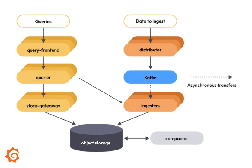
The ingest-storage architecture introduced in Grafana Labs’ post on Mimir’s redesigned architecture. Kafka acts as an asynchronous buffer between ingestion and queries, decoupling the write and read paths.
To summarize, we expected the following benefits:
- Prevent ingester failures from immediately causing write failures
- Use Kafka lag as a buffer to reduce 429 responses caused by distributor-to-ingester backpressure
- Move to ingest storage, the preferred architecture in Mimir v3
2. The First Thing We Noticed: Much Lower Ingester Resource Usage
The most striking change in our proof of concept was ingester resource usage. We dual-wrote the same remote-write traffic to the classic and ingest-storage stacks. Distributor input was almost identical, but the amount processed by the ingesters differed dramatically. In the central monitoring cluster at the time, the distributor ingestion rate was approximately 313k samples/s for the classic stack and 308k samples/s for the Kafka PoC. The ingester metrics, however, looked like this:
| Metric | Classic | Ingest-storage PoC | Difference |
|---|---|---|---|
| Total ingester CPU | 12.42 cores | 3.07 cores | -75% |
| Total ingester memory | 148.8 GB | 46.4 GB | -69% |
| Ingester ingested samples/s | 941k/s | 309k/s | About one-third |
| Ingester in-memory series | 35.17M | 11.42M | About one-third |
| Ingester PV usage | 213.16 GiB | 63.92 GiB | About one-third |
The reason was the replication factor. Following Grafana Labs’ recommended production configuration, our classic stack used RF=3. A distributor therefore pushed each series to three ingesters, so an input rate of 313k samples/s became approximately 941k samples/s across all ingesters. With ingest storage, the distributor writes a series to only one Kafka partition. Internally, Mimir’s partition ring behaves as though ReplicationFactor() = 1 on the write path. Kafka topic replication, rather than Mimir’s ingester replication factor, provides write durability.
There is an important nuance. Saying that “RF becomes 1” in ingest storage mainly describes the distributor write path and the series held by each ingester. With zone-aware replication, ingester owners in multiple zones consume the same Kafka partition. Each zone owner may therefore upload its own block to S3, and the compactor removes those duplicates through vertical compaction, just as it does in the classic architecture.
The point is not that ingest storage produces no duplicate blocks in S3. The more important change is that the metric-series load held in each ingester’s in-memory TSDB head and local disk falls from the classic RF=3 fan-out model to one copy per partition.
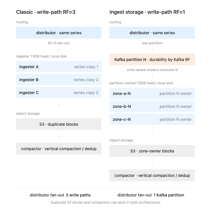
The classic architecture does not return three copies of every query result. Read-time deduplication and the compactor’s vertical compaction handle duplicate blocks. In ingest storage, the compactor likewise handles blocks uploaded by zone-aware owners. The difference lies earlier in the pipeline. In the classic architecture, the distributor fans the same series out with RF=3 on the write path, and the ingesters must accept those writes concurrently. In ingest storage, the distributor writes to one Kafka partition and the ingesters asynchronously catch up with the partitions they own. This substantially reduces the in-memory and local-disk load that ingesters must handle immediately.
That was a significant benefit, but it also transferred an equally significant responsibility to Kafka. Durability and write availability for recent data now depend heavily on Kafka topic replication, broker availability, producer settings, and consumer-lag operations.
3. Mimir Does Not Use Kafka Like a Typical Consumer Group
This is the point I most want to emphasize.
When we think of a typical Kafka application, we usually picture something like this:
flowchart LR
    K["Kafka topic<br/>partitions 0..N"] --> CG["consumer group"]
    CG --> C1["consumer-1<br/>partition 0,1"]
    CG --> C2["consumer-2<br/>partition 2,3"]
    CG --> C3["consumer-3<br/>partition 4,5"]
When consumers are added or removed, the group coordinator recalculates partition assignments. A consumer may read several partitions, and assignments can change as the group scales out.
Mimir’s ingest-storage ingesters do not work this way. As the official documentation states, each ingester consumes from exactly one partition. The partition assignment is extracted from the instance ID. An instance ID of ingester-zone-a-13 reads partition 13, while mimir-write-zone-b-7 reads partition 7. As a regular expression, the -([0-9]+)$ suffix of the instance ID becomes the partition number.
In other words, the Kubernetes StatefulSet ordinal effectively becomes the Kafka partition number.
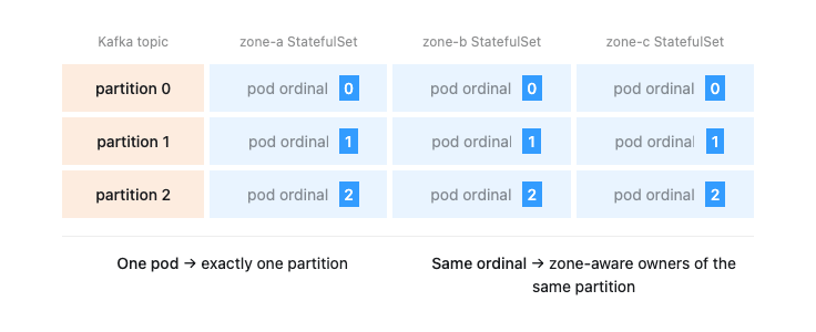
Two aspects of this model are unusual.
-
First, one ingester does not divide its work across multiple partitions.
zone-a-0reads only partition 0, andzone-a-1reads only partition 1. -
Second, multiple ingesters consume the same partition for high availability. For example,
zone-a-0,zone-b-0, andzone-c-0all read partition 0. From Kafka’s consumer-group perspective, each ingester has its own offset and reads the same partition.
Mimir’s read path is built around this model. The querier consults the partitions ring to determine which partition contains the required series, then consults the ingesters ring to select one healthy ingester that owns that partition. In ingest storage, the quorum per partition effectively behaves like 1. If several ingesters own the same partition, reading from one of them is enough.
As a result, “adding more ingester replicas” in Mimir ingest storage does not mean freely increasing the worker count as it would in a typical Kafka consumer application. The partition count, StatefulSet ordinals, number of zones, and number of owners per partition must all align.
4. Decide the Partition and Ingester Replica Counts Up Front
Because of this model, the first decision is the number of partitions in the Kafka topic.
Mimir’s documentation says the topic needs at least as many partitions as there are ingesters in one zone. The reason is simple: because an ingester’s ordinal becomes its partition number, Kafka partition 6 must exist before you can run an ingester that reads partition 6.
In our PoC, the Kafka topic had seven partitions and the ingesters used a three-zone, zone-aware deployment. With the Helm chart, setting ingester.replicas: 21 rendered three StatefulSets with seven replicas each.
Kafka partitions: 7
Zones: 3

mimir-ingester-zone-a replicas: 7  -> partition 0..6
mimir-ingester-zone-b replicas: 7  -> partition 0..6
mimir-ingester-zone-c replicas: 7  -> partition 0..6

Total ingester pods: 21
Partition owners: normally 3 owners per partition
One setting we initially found confusing was ingester.partition_ring.min_partition_owners_count. It means “the minimum number of owners that must attach before a partition becomes ACTIVE.” It does not create partitions or arrange pods. For transitions between PENDING, ACTIVE, and INACTIVE, see the official Grafana documentation on the partitions ring lifecycle. Section 7 below revisits this lifecycle from a scale-in perspective.
For example, running one StatefulSet with 12 replicas and setting min_partition_owners_count: 2 does not automatically produce a “6 partitions × 2 owners” deployment. Multiple StatefulSets must contain ingesters with the same partition number, which with the stock Helm chart means a layout such as zone-aware StatefulSets with matching ordinals.
The Helm chart introduced another practical constraint. In the mimir-distributed 6.0.6 chart we used, template validation required at least three zones when zoneAwareReplication.enabled=true. Although Mimir’s model permits two owners per partition, producing a clean two-zone, RF=2 deployment through chart values alone was difficult. We chose three zones to avoid patching the chart.
The lesson was clear:
Design Mimir ingest-storage replicas as “partition count × zone/owner count,” not as a consumer count.
5. Why Did Mimir Choose These Constraints?
At this point, one question naturally comes to mind:
Why does Mimir tie ingester ordinals so tightly to partition numbers instead of allowing each ingester to consume multiple Kafka partitions dynamically?
We were accustomed to multiple consumers joining one consumer group and partitions moving among them through rebalances. In Mimir ingest storage, however, allowing partitions to move freely between ingesters would be problematic.
The key is that an ingester is not merely a Kafka consumer. It is also a stateful component on the read path. The distributor shards series into Kafka partitions on the write path. An ingester consumes one of those partitions and applies the data to its in-memory TSDB and local WAL or blocks. When a querier reads recent data, it queries the ingesters as well as object storage. It does not pick an arbitrary ingester. Mimir uses its hash rings as the source of truth. The querier uses the partitions ring to determine which partition holds a series, then the ingesters ring to find a healthy owner of that partition.
flowchart LR
    Q["querier"] --> PR["partitions ring<br/>series token -> partition"]
    Q --> IR["ingesters ring<br/>partition owner -> ingester address"]
    PR --> P["partition N"]
    IR --> I["ingester zone-a-N / zone-b-N / zone-c-N"]
    Q -->|"read recent samples"| I
Partition ownership must therefore remain stable and discoverable on the read path. If assignments moved freely on every rebalance, as in a typical Kafka consumer group, Mimir’s partitions and ingesters rings would need to represent and propagate every change in which ingester holds the latest data for each partition. This observation alone does not prove that an ingester must consume exactly one partition, but it does make one point clear: a Kafka partition is not something that can move transparently between servers as it can in an ordinary consumer group.
Mimir appears to have chosen the simpler operational model. Each ingester consumes exactly one partition, and the ordinal at the end of its instance ID determines which one. At initial setup, you forecast the required capacity and choose the Kafka topic’s partition count and the number of ingester replicas in each zone. When you later need more capacity, you increment the partition count and ingester count together.
partition 0  <->  ingester-zone-a-0 / zone-b-0 / zone-c-0
partition 1  <->  ingester-zone-a-1 / zone-b-1 / zone-c-1
partition 2  <->  ingester-zone-a-2 / zone-b-2 / zone-c-2
...
Strictly speaking, partition and ingester counts do not always have to match. Operationally, however, keeping them equal is the simplest approach.
- If there are more partitions than ingesters, the extra partitions have no owners. They do not become ACTIVE write/read targets in the partitions ring, so they are effectively unused.
- If there are more ingesters than partitions, an extra ingester cannot find the Kafka partition corresponding to its ordinal. It may wait during startup or fail because it has no partition to consume.
This unusual design can be understood as the combination of two goals. One is to continue using the hash-ring model that Grafana Mimir, Loki, and related systems have long used as the source of truth for state and ownership. The other is to simplify the parameters an operator must coordinate. By declaring ownership through Mimir’s rings and StatefulSet ordinals rather than delegating it to Kafka consumer-group rebalances, operators can design and extend capacity around a simple rule: align the partition count with the ingester ordinals.
In summary:
- A Mimir ingester is not just a consumer; it also serves recent data on the read path.
- A querier uses the hash rings to determine which partition and ingester to read.
- Partition ownership must therefore be managed explicitly in Mimir’s rings rather than moving implicitly through Kafka consumer-group rebalances.
- This constraint lets operators design capacity around the simple model of mapping partition counts one-to-one with ingester ordinals.
6. A New Consumer Group Can Cause a Backfill Storm
The most alarming issue during our PoC appeared when we added ingesters in a new zone. They replayed the entire Kafka backlog at once, placing heavy load on both the MSK brokers and the ingesters.
The cause was a change in StatefulSet and pod names. During the move to zone-aware replication, pod names changed from mimir-ingester-* to mimir-ingester-zone-a/b/c-*. A Mimir ingester creates its consumer group from its instance ID, so a name change creates a new consumer group with no existing committed offset.
The meaning of the startup consume position was the next problem.
The near-default value at the time, last-offset, can be understood as “resume at the last committed offset when one exists.” A completely new consumer group, however, has no committed offset. In that case, it may unexpectedly begin reading from the start of the partition.
sequenceDiagram
    participant I as New ingester<br/>new instance ID
    participant K as Kafka partition
    participant M as MSK broker

    I->>K: look up consumer group offset
    K-->>I: no committed offset
    Note over I: startup position fallback<br/>consume from partition start
    I->>M: surge of historical backlog Fetch requests
    M-->>I: Fetch throttling / increased BytesOut
    Note over I: receive delay / lag rises<br/>readiness is delayed
We observed the following symptoms:
- Ingester logs resembling
starting consumption from partition start because no offset has been found - MSK broker
Fetchthrottling - A sharp increase in BytesOut
- Higher ingester receive delay and consumer lag
- Delayed readiness (when lag exceeds 15 seconds, consumption continues but readiness becomes false)
Our operational goal was to start zone-aware ingesters, not to reprocess the historical backlog, so in the PoC we explicitly set the startup position to end. New consumer groups started at the latest offset and intentionally skipped the backlog replay.
The lessons were:
- Check whether changing a StatefulSet name, pod name, or instance ID will also change the consumer group.
- Explicitly choose where a new consumer group should start when it has no committed offset.
endavoids a backfill storm, but deliberately skips older data that remains only in Kafka.timestampcan be useful when you need a clearly defined cutover point.
Adding Kafka as a buffer does not automatically make the system safe. A buffer absorbs failures, but a misconfigured consumer can overload the Kafka cluster and create a different incident.
7. Scale-in Is More Than Reducing Replicas
Scale-out is relatively intuitive. If enough Kafka partitions exist and the partition corresponding to a new ordinal is available, you can add ingesters. You still need to account for the partition-ring lifecycle and the time required to propagate the Pending-to-Active transition.
Scale-in required more thought. Partitions in the ingest-storage architecture have a lifecycle:
Pending: not yet available for reads or writesActive: normal state; distributors write and queriers readInactive: distributors no longer write, but queriers must still read
For scale-in, new writes to the target partition must stop. The ingester can only be removed after the data it already consumed becomes queryable from object storage.
Grafana’s documentation explains that the rollout-operator coordinates this process in production. When we tested the default combination of the Helm chart and rollout-operator, however, we found that simply enabling it did not fully automate safe scale-in for our use case.
First, prepareDownscale: true configures the chart to call a prepare endpoint when a StatefulSet scale-in is admitted. In the chart version we used, however, the path was hard-coded to ingester/prepare-shutdown. The primitive we wanted for ingest-storage partition scale-in was /ingester/prepare-partition-downscale. This endpoint changes the partition from ACTIVE to INACTIVE, causing distributors to stop sending writes to it.
sequenceDiagram
    participant O as Operator / Runbook
    participant I as Ingester partition owner
    participant R as Partitions ring
    participant D as Distributor
    participant Q as Querier

    O->>I: POST /ingester/prepare-partition-downscale
    I->>R: partition ACTIVE -> INACTIVE
    D->>R: look up active partitions
    Note over D: stop new writes to inactive partition
    Q->>R: look up read partitions
    Note over Q: inactive partition remains a read target
    O->>O: wait long enough / verify metrics
    O->>I: prepare shutdown / scale in
Another confusing point was the rollout-operator’s zone-aware scale-in ordering and its 12-hour gate. With grafana.com/min-time-between-zones-downscale=12h, the admission webhook prevents one zone from scaling down immediately after another. This is a useful safeguard, but the webhook checks the last-downscale values of the other StatefulSets in the same rollout group, not merely the target zone’s own last downscale. The rollout-downscale-leader annotation also creates a follower chain such as zone-a → zone-b → zone-c, in which each follower tracks the leader’s replica count.
If you manually reduce only zone-c in a test, it may pass admission temporarily, but the controller can restore its replica count from the leader’s state. A proper test must account for the leader/follower ordering created by the chart.
Our conclusion at the time was:
Mimir ingest storage provides protective primitives for scale-in, but the default
mimir-distributedchart and rollout-operator configuration did not fully automate the “stop partition writes → wait for a sufficient drain period → shut down” procedure we needed.
We wrote the following scale-in runbook:
- Call
/ingester/prepare-partition-downscale. - Verify at the distributor that writes to the target partition number have stopped.
- Verify that reader requests, offsets, and lag have stopped changing.
- Reduce replicas after a sufficient waiting period.
8. Read Consistency and Lag Become Operational Metrics
With ingest storage, a distributor returns success to the client after writing to Kafka. The ingesters consume from Kafka asynchronously. You therefore cannot always assume that data will be visible on the query path immediately after a successful write.
Under normal conditions, end-to-end ingestion latency should typically remain below one second. Kafka broker problems, ingester restarts, or backfills can increase lag. For queries that require strong read consistency, Mimir supports the X-Read-Consistency: strong header. The query frontend retrieves the latest offset for each Kafka partition and propagates it through the read path. The query waits until the ingester has consumed through that offset before executing.
This is important for components such as rulers that require read-after-write behavior. When lag is high, however, it can increase query latency or cause timeouts.
After adopting ingest storage, we therefore had to watch more than ingester CPU and memory. The following signals became increasingly important:
- Kafka broker BytesIn / BytesOut
- Broker Fetch throttling
- Consumer lag by partition
cortex_ingest_storage_reader_receive_delay_secondscortex_ingest_storage_reader_last_consumed_offset- Ingester startup lag and delayed readiness
- Distributor Kafka produce errors and latency
The classic architecture trained us to ask whether ingesters were accepting writes. With ingest storage, we must ask both whether data is being stored in Kafka successfully and how quickly each ingester is catching up with its partition.
9. What I Would Check Before Adopting It
If I could return to the start of the project, these are the questions I would answer first.
Kafka / MSK
- How many topic partitions should we start with?
- When will we need to increase the partition count?
- How should we configure the topic replication factor, minimum ISR, and broker placement across availability zones?
- Are Kafka’s
message.max.bytesand the topic’smax.message.byteslarge enough for Mimir’s default record size? - Does our Mimir version support the authentication method we plan to use?
- Have we prepared alerts for MSK broker BytesOut and Fetch throttling?
Mimir Ingester Placement
- Does every ingester instance ID end in
-<partition number>? - Is the mapping between StatefulSet ordinals and Kafka partition numbers explicit?
- How many zones will the zone-aware deployment use?
- What should the minimum owner count per partition be?
Migration / Rollout
- Will changing from the old ingester names to new ones create new consumer groups?
- Where will a new consumer group start when it has no committed offset?
- If a backfill is required, do the brokers and ingesters have enough capacity?
- If a backfill is not required, have we explicitly set
endortimestamp?
Scale-in
- What procedure will call
/ingester/prepare-partition-downscale? - How long should we wait after a partition becomes
INACTIVE? - Which metrics determine that draining is complete?
- Do we understand the rollout-operator’s admission webhook, leader/follower annotations, and 12-hour gate?
Conclusion
Mimir’s ingest-storage architecture is not simply a matter of adding Kafka. It changes the responsibilities of the write and read paths, moves replication from ingesters to Kafka, and shifts the ingester’s role from “a stateful writer participating in write quorum” toward “a partition owner that consumes Kafka and serves recent data on the query path.”
The benefits were clear. In our PoC, ingester CPU and memory dropped substantially under the same ingestion traffic, and Kafka gave us a way to absorb backpressure between distributors and ingesters. We also greatly reduced the duplicate TSDB-head, WAL, and block costs caused by the classic architecture’s RF=3 fan-out. Those savings did not come for free. Kafka or MSK adds broker, storage, network-traffic, and operational costs. The PoC numbers in this post show the resources saved in the ingester tier; they do not mean that the total cost of the monitoring stack, including Kafka, fell by the same amount. Evaluating the actual cost impact requires comparing the ingester savings with the cost of operating Kafka.
The operational model changes along with the architecture. The most important lessons were that ingester pod ordinals map one-to-one to Kafka partition numbers, that a new instance ID can create a new consumer group and introduce offset problems, and that scale-in requires an understanding of partition lifecycles and rollout-operator behavior.